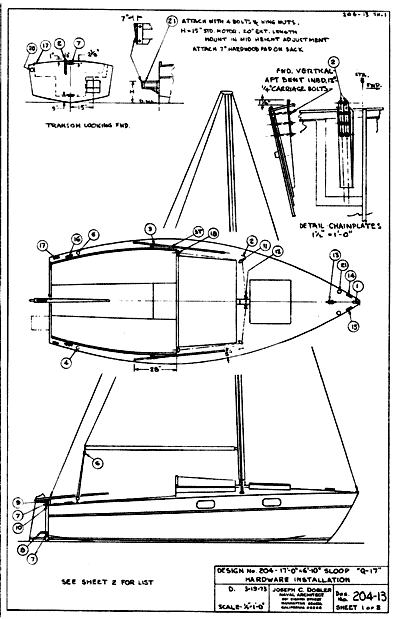
The Q-17 is a plywood sloop designed for the amateur builder. The construction is Taped Seam with FRP sheathing, which means that it is permanently tight and a strong, one piece structure. All parts are detailed so that they may be prefabricated. No lofting is required. No strongback or jig is required and there is no attachment to the floor.
There are two berths below and the cockpit will sleep two. A boom tent will make the cockpit into a comfortable cabin, which may be preferred to sleeping below, or perhaps a place for the parents to get a little distance from the kids. Galley gear is in two portbable boxes which may be removed to the cockpit or ashore for use, if that is more convenient. A portable ice box may be made to fit in the forward end of the
cockpit well.
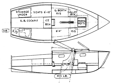
A small outboard motor may be attached to a folding or removable bracket on the transom, and may be stowed under the cockpit seat when not in use. Oars, preferably jointed, may be used with with the ice box as a seat.
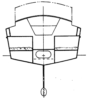
The ballast keel is retractable, using an automobile bumper jack. It is possible to flatten the ballast vertically, giving more of a "winged keel" effect and reducing the draft, in up or down position, by two or three inches. Data on this is not available at present, but will be made available if there is a demand.
Here is a letter from Joe Dobler to Mike W, a prospective builder:
17 November 1994
Mike W
Dear Mike:
Here, finally, is some info on the Mini-Cruiser, Q-17. It was designed for Bruce Clark, who did some business in boat plans and kits as Quicksilver Boats. The last address I had for him was at 249 Warfield Avenue, Venice, Florida 33695. He is long since out of business. I would guess that he may no longer be with us.
Rather than a writeup, I enclose a copy of a description from Bruce's brochure (see below). You may disregard the part about me, but the part about the boat is pretty well on track. The talk about displacement and capacity might be confusing. Actually, the displacement to the designed W.L. is 2010 lb. and the estimated boat weight is 1100 lb., leaving about 910 lb. disposable at that WL. At a W.L. two inches below the D.W.L. the displacement is 1365 lb.
The construction is Taped Seam Plywood with fiberglass-epoxy sheathing on the outside. It makes a boat that is light, strong, permanently tight and very long lasting with reasonable care. The plans are large scale and very completely detailed, more so than I have done any boat since. No boatbuilding expertise is needed, there is no jig or strongback and nothing is attached to the floor. No lofting is required. The plan fee is $125.
I enclose study sheets of some other designs that I think you may find interesting. The âPresto Systemâ came along after No. 204, but it could be readily adapted. It does help to get everything located right. In some areas it helps to control the spring in the plywood.
Best regards,
Joe Dobler

From Bruce Clark's Brochure:
Quicksilver "Q-17" trailable cruising sailboat is number 204 from the board of Joseph C. Dobler, a retired aeronautical engineer who is also the moat original and versatile naval architect I know of. Hundreds of boats have been built from his designs by both amateur and professional builders; his designs include conventional sailboats and cruising sailboats, catamarans and trimarans up to 40 feet or so long. The Quicksilver "Q-17" was designed to my specifications to incorporate the latest and best in modern boat design and construction and to be as easy to build and inexpensive as possible, light, trailable, but fast, seaworthy, self-righting, and with self-bailing cockpit.
It is also outstanding in looks, and as roomy as it is possible to make a cruising boat of it's size without it becoming a tub. Length is 17', beam 6' 10", draft 1' 7" with drop keel up, 3' 7" with keel down. Weight of hull and rig is about 700 lb., ballast keel 400 lb., design displacement 2010 Lb., or capacity to design water line, 910 lb., approximately. Construction is the simplest possible, using 3/8" plywood and fiber-glass with bulkheads taking the. place of frames, attached with fiberglass tape, to reduce fitting problems. There are no internal stringers, the seat and bunk fronts form a girder which stiffens the bottom for trailer loads. The rub rail at the lower sheer doubles as an .external stringer. In spite of its small size, this boat has a really surprising amount of room. The raised deck design is simpler and stronger than a regular cabin, yet roomier; it gives sitting headroom, and the large lifting cabin top and forward hatch give additional room where it is most needed. Bunks can be either forward, or quarter bunks partly under the cockpit seats, as there is a platform on each side 11.5' long. Cockpit seats are 6.5' long, for those who prefer to sleep in the open. The keel is raised with auto jack. The keel trunk ties into the roof for stiffness and to support the mast. Detailed instructions are included with the plans.
Sample page from plans - click to enlarge
Included in Q-17 plans are the following:
Booklet:
Table of Contents
P-7 C.B. Trunk construction (2 pages)
Taped Seam Procedure (2 pages)
Building Instructions (3 pages)
GS 102 - Plywood
Bill of MaterialsDrawings
SD-CSH-1 - Hatch Detail
204-1 - General Arrangement
204-2 - Lines
204-3 - Construction Plan & Profile
204-4 - Construction Sections
204-5 - Plywood Layout-Planking & Web
204-6 - Keel Trunk
204-7 - Plywood Layout-Seats, Soles & Coamings
204-8 - Plywood Layout-Main Structure
204-9 - Deck Layout & Installation
204-10 - Keel Assembly & Installation
204-11 - Keel Plate
204-12 - Keel Ballast
204-13 - Sheet 1 - Deck Hardware - Layout
204-13 - Sheet 2 - Deck Hardware - Explanation
204-14 - Hatches, Rudder, Tiller & Boxes
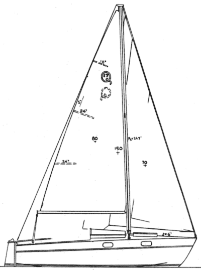
204-15 - Sail Plan
204-16 - Spars & Rigging
204-17 - Flotation
204-18 - Furnishings
204-19 - Ladder
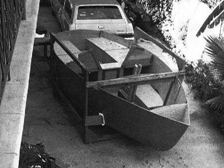
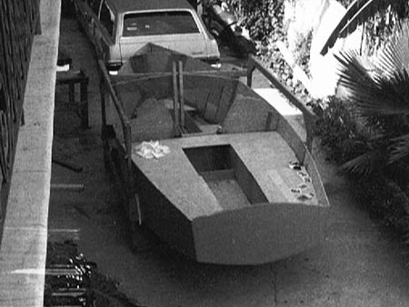
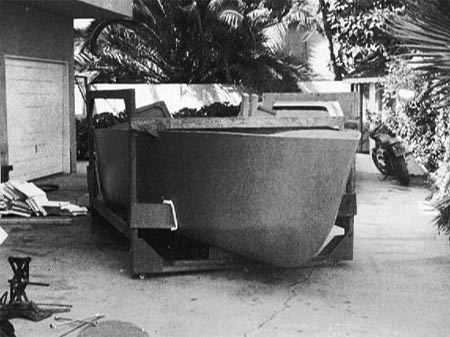
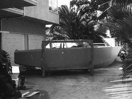
Here are some photos that Tom Setum sent - They are of a Q-17 under construction but the builder and location are unknown:
Q 17
LOA=17'0" - 5.182M
LWL=15'3" - 4.648M
Beam=6'10" - 2.083M
Draft, keel up=1'8" - 0.508M
Draft, keel dn=3'8" - 1.117M
Plywood Taped Seam Construction


